Hi all,
Just got my RaZberry and I'm a bit confused on how to hook it up. I have a Raspberry Pi B+ and the manual states it should hook up to GPIO 17-26, sounds easy enough. The pictures I find online, however, seem to contradict the pin out diagram on the official Raspberry site for the Model B:
http://www.raspberrypi.org/documentation/usage/gpio/
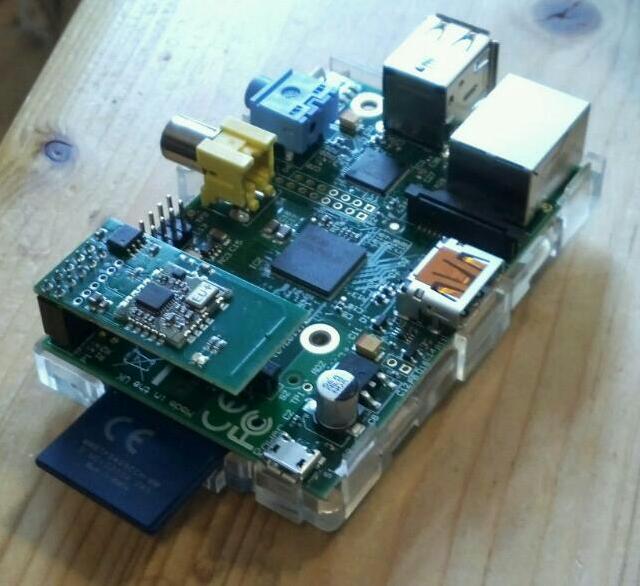
According to the diagram, GPIO 17-26 should be closest to the Video RCA plug, but all the pictures seem to put it on the other side, which would be 1-10 (which doesn't make sense, as that's 2x 5v, 1x 3.3v, 2x GND and 5x GPIO).
Can someone please clear up the confusion for me? Thanks!
GPIO confusion
GPIO confusion
Last edited by RajenK on 17 Nov 2014 22:28, edited 1 time in total.
Re: GPIO confusion
To make matters even more confusing, the image on the included instruction shows a Model B+ with the RaZberry board connected to the far edge as well:
That also seems to be the same 2x 5v, 1x 3.3v, 2x GND, 5x GPIO combo (http://pi4j.com/pins/model-b-plus.html).
Re: GPIO confusion
Where did you read about GPIO 17-26 pins? I've looked over pdfs on the site, and they never mention pin numbers.
You should hook it up as shown in the pictures (pins 1-10).
Re: GPIO confusion
Check out the picture I took of the instruction that came with the board (second post): "(it uses the GPIO Pins 17-26)". So, that's incorrect and it indeed hooks up to the 2x 5v, 1x 3.3v, 2x GND, 5x GPIO combination?pofs wrote:Where did you read about GPIO 17-26 pins? I've looked over pdfs on the site, and they never mention pin numbers.
You should hook it up as shown in the pictures (pins 1-10).
Re: GPIO confusion
Well the confusion may arise from the fact that the functionality of the pins are programmable. (See http://wiringpi.com/pins/special-pin-functions/) So that may lead to misleading naming conventions on the edge connector. Actually GPIO X is defined on the SOC chip, and may be mapped to a specific pin on the edge connectors.
It is very confusing indeed. One probably has to be of British origin to really understand and appreciate
Took me quite a while when I made thehttp://razberry.zwave.me/index.php?id=3
It is very confusing indeed. One probably has to be of British origin to really understand and appreciate
Took me quite a while when I made thehttp://razberry.zwave.me/index.php?id=3
Since 29-12-2016 I am no longer a moderator for this forum
Re: GPIO confusion
Interesting Weird that it states this by default, though. Either way I got it working now. Thanks!pz1 wrote:Well the confusion may arise from the fact that the functionality of the pins are programmable. (See http://wiringpi.com/pins/special-pin-functions/) So that may lead to misleading naming conventions on the edge connector. Actually GPIO X is defined on the SOC chip, and may be mapped to a specific pin on the edge connectors.
It is very confusing indeed. One probably has to be of British origin to really understand and appreciate
Took me quite a while when I made thehttp://razberry.zwave.me/index.php?id=3
Re: GPIO confusion
Thanks for the feedback, we will fix it in the PDF coming with the device
-
- Posts: 5
- Joined: 29 Nov 2014 01:19
Re: GPIO confusion
Interesting. So the board should be plugged in on the opposite end shown in the documentation?
I tried it both ways and can't get it to work either way but I don't want to troubleshoot further until I know which one is right.
Re: GPIO confusion
The position as in the picture is correctOneFastt997 wrote:I tried it both ways and can't get it to work either way but I don't want to troubleshoot further until I know which one is right.
Since 29-12-2016 I am no longer a moderator for this forum